[phpBB Debug] PHP Warning: in file [ROOT]/includes/functions_content.php on line 1014: Undefined array key 3 [phpBB Debug] PHP Warning: in file [ROOT]/includes/functions_content.php on line 1014: Undefined array key 3 [phpBB Debug] PHP Warning: in file [ROOT]/includes/functions_content.php on line 1014: Undefined array key 3 [phpBB Debug] PHP Warning: in file [ROOT]/includes/functions_content.php on line 1014: Undefined array key 3 [phpBB Debug] PHP Warning: in file [ROOT]/includes/functions.php on line 4130: Cannot modify header information - headers already sent by (output started at [ROOT]/includes/functions.php:3009) [phpBB Debug] PHP Warning: in file [ROOT]/includes/functions.php on line 4130: Cannot modify header information - headers already sent by (output started at [ROOT]/includes/functions.php:3009) [phpBB Debug] PHP Warning: in file [ROOT]/includes/functions.php on line 4130: Cannot modify header information - headers already sent by (output started at [ROOT]/includes/functions.php:3009) [phpBB Debug] PHP Warning: in file [ROOT]/includes/functions.php on line 4130: Cannot modify header information - headers already sent by (output started at [ROOT]/includes/functions.php:3009) Speed controller design - RobotWars101
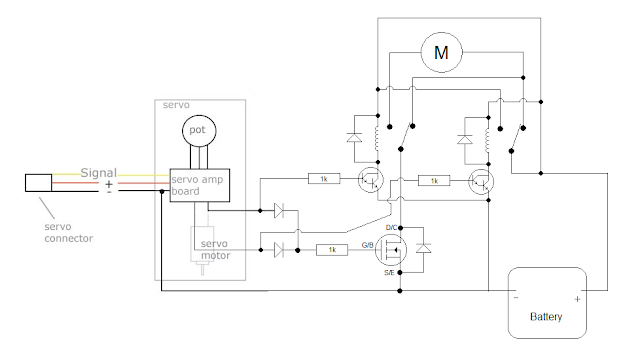
I think I've come up with a way to add relay reversing to this plane esc.
What I would like to know is can anyone see anything wrong with it that could make it not work, break or be dangerous?
A rough estimate on buying enough components for two controllers from technobots comes to about £26 with vat and the cheap postage. However, about £10 of that is the servos which can be bought for less elsewhere or ones with a dead motor could be used. I'm sure if you were to shop around and/or already have some of the parts the cost will come down considerably.
If you are going to test this I would current limit your battery to avoid releasing the magic smoke. I haven't gone through it in much detail but my feeling is the motor is not wired correctly. Typically the motor is connected to the common on the relay.
Also if the fet closes faster than the darlington you may short the battery for a short time.
I forgot about the Darlington's, they were the only way I could stop the 555 timer that I was using to simulate the output of a servo in yenka from releasing virtual magic smoke as soon as I turned it on.
So a rewire of the relays, up the value of the mosfet's gate resistor to decrease it's 'on' speed and lower the value of the Darlington base resistors/replace them with an normal transistor to increase it's 'on' speed should make it feasible.
The motor wiring is wrong in the schematic. The top-left contact of the right-hand relay should be connected to the left terminal of the motor (not to the battery positive as shown).
The darlington transistors may not be necessary depending on the battery voltage and relay coil resistance. Small FETs should also be suitable.
Like all relay reversing systems it is vulnerable to switching direction whilst the motor is still turning. In this case the motor back-EMF can easily destroy the relays by arcing.
To avoid the relay problems you would have to design a full H-bridge circuit which is quite easy to interface to a servo board. I've done it on a much smaller scale and it works OK. Downside is the complexity (and maybe the cost) of the full H-bridge.
Whoops I should really have picked up that wiring error.
Do you think an RC snubber circuit could protect the relays from the back emf?
If not would a varistor do the trick as from what I understand it acts like a pair of back to back zener diodes so under normal operating conditions it doesn't conduct but when there is a large voltage spike that excedes the zener voltage it acts as a bidirectional flyback diode.
An RC snubber should work. I don't have much experience of them but I do know they can be difficult to get to work properly. They are easy to destroy if the dissipation gets too high!
Never seen a varistor used in this application, I'm not sure if the energy rating is high enough?